This post is likely to bore everyone except that one fella who may someday stumble onto it looking for tips for doing something similar. Sorry everyone…
My house electrical system is not too different than what you will find on larger motorhomes. There is 50 amp shore power, 50 amp generator power (no generator yet but there will be), a large lithium battery bank, an inverter (converts DC battery power to 120 volt AC power), and solar power. This all goes together in a fairly simple way…
Ha! Ok – not so simple way… 🙂
First, a tiny bit of background info. A 50 amp RV circuit is two, 50 amp legs of 120 volts each. A 30 or 20 amp RV circuit is one 30 (or 20) amp leg of 120 volts. So, a 50 amp RV circuit is a lot more power than a 30 amp circuit. Two 50 amp, 120 volt circuits compared to one 30 amp, 120 volt circuit.
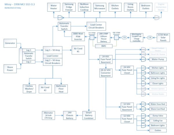
Note from JD: The following is the latest/greatest version of the electrical system (08/08/2018).
Assuming I am connected to 50 amp shore power or the generator is running, power is coming in on two legs (120 volt, 50 amp each). Call these Leg 1 and Leg 2. When connected to shore power that is less than 50 amp (30 or 20), leg 1 has power and leg 2 MAY have power. Many dogbone type plug adapters (e.g. 50 amp connector to a 30 amp connector) will bridge leg 1 and leg 2. No power on Leg 2 means anything connected to it is inoperable. If leg 2 is powered while connected to less than 50 amp power, one has to understand that the a small amount of power is being distributed to a large number of items so many power management is necessary (such as not turning on both air conditioners).
Each of these feed into a transfer switch because we can have only one of them supplying power at once. The generator takes precedence over shore power.
The Leg 2 output from this switch goes to a load center (circuit breaker panel) that supplies power to only a few items that are available when that power is available. This is the second air conditioner, clothes washer, and clothes dryer.
The Leg 1 output from this transfer switch goes to a second transfer switch. The other input to this second transfer switch is the inverter. In my case, the shore/generator input takes precedence over the inverter input.
The output from the second transfer switch goes to a second load center. 120 volt power for the house is distributed from here. However; there is a little trick. Power for the battery charger is taken from Leg 1 BEFORE the second transfer switch. The result of this is that if shore or generator power is available, the battery charger is on. If it is not available and we are running on battery/Inverter power, the battery charger is not on and it does not receive power from the inverter (an electrical loop). I have done the same with the water heater and primary air conditioner as I do not want these being powered by the inverter (and batteries).
The solar panels are wired into the MPPT charge controller and its output is direct to the batteries.
The major parts used are:
- Morningstar TS-MPPT-60 solar charge controller
- Progressive Dynamics 25 amp 24 volt Lithium Charger/Converter PD9125-24LV (ordered, not installed yet)
Progressive Dynamics 40 amp 24 volt Converter/Charger PD9240-24- Progressive Dynamics Automatic Transfer Switch PD52DCSV (transfer switch #1)
- WFCO T57 50 Amp Transfer Switch (transfer switch #2)
- Square D 12-Circuit 6-Space 100-Amp Main Lug Load Center (two of them)
- Go Power GP-ISW3000-24 3000 Watt Pure Sine Wave Inverter
The 120VAC load centers and circuit breakers are standard items found at any home improvement/building center. I picked one that was compact and matched my needs. Romex was used for the circuits, 14/2 for some up to 10/2 for the more power hungry circuits. Nothing complex about that side of the system.
I thoroughly enjoy learning new things and this electrical system has provided some learning opportunities! 🙂
Some related posts:
Solar Charging System for Missy
Lithium Battery (LFMP) for Missy


Where’s that cute retiree when you need her?
Somebody drove a big bus thru one of her flower gardens the other day and she has been busy “repairing” the mess. 🙁
I would love to help put one of those systems together. It is hard for me to understand all of it without the hands on. I have to give this some thought. Are you using 24 volt because Missy had a 24 volt system?
Great question Pete! Stay tuned! I understand about the hands on – I’m the same way and really love messing with these types of things.
your link took me to a modified wave inverter [see Q&A]. are you using that for everything including electronics? For how many yrs? modified is much cheaper than full sine wave, but i dont want to damage my computer, microwave, or fridge.
Howdy DM! I just updated that post. I am now using a Go Power! 3000 watt pure sine wave inverter. My Samsung refrigerator did not seem to like the MSW (was very noisy) plus I learned that MSW is hard on inductive motors. All seems happy with the PSW inverter.
is your
WAGAN 5,000W ProLine Power Inverter (24V) WA37444
a modified wave type?
how does your fridge etc. work on that? i have been told to get a full wave at 10x the cost!
and is Wagan long lived?
Sorry about that DM, your earlier question (and this one) went into the spam folder.